Selecting the hardness grade in Hardox wear-resistant steels
Hardox 450 or 500: how the wear mechanism, the return on each hardness step and workshop processing determine the correct grade for each application.
News
Laser, plasma or oxyfuel: how thickness, EN ISO 9013 quality class and downstream processing determine the cutting process and the cost of cutting to drawing.
Topics
laser plate cuttingplasma cuttingoxyfuel cuttingEN ISO 9013heat-affected zoneplate cutting to drawingnesting and offcut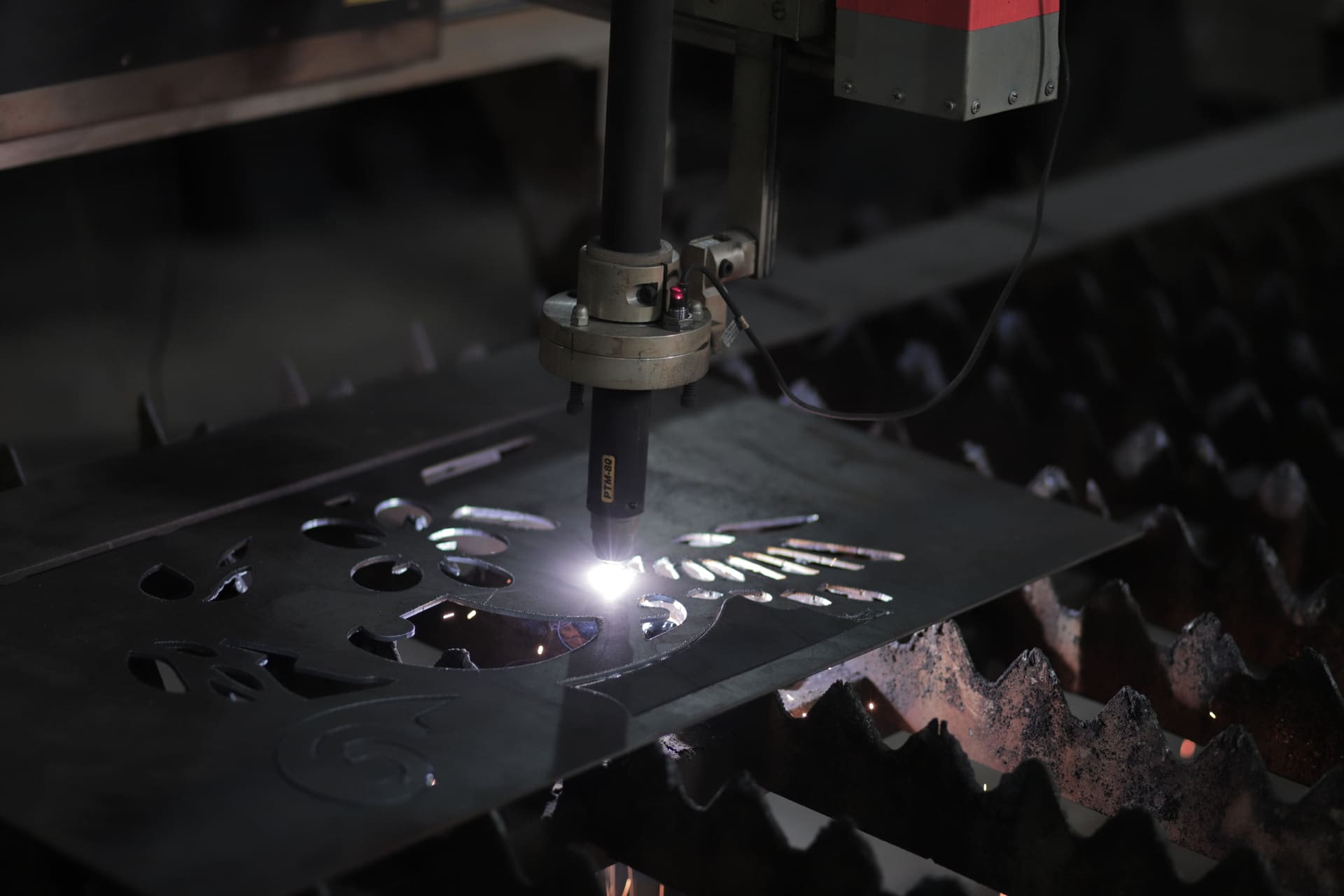
The process is determined by three variables, in this order: the thickness of the material, the quality class required at the edge and the downstream processing planned for the part. The name of the technology is the consequence of this reasoning. In most real cases, once the three variables are known the choice is forced and there is nothing left to compare.
Requesting laser by default stems from the assumption that it is the most precise process in absolute terms. On thin gauges the assumption holds. Beyond a certain threshold the process is simply not available, and in the intermediate band the comparison shifts to parameters the drawing often does not specify — first of all the tolerance actually needed.
The application ranges overlap less than the comparison suggests. EN ISO 9013 indicates a different thickness interval for each process, and industrial practice narrows those intervals further on economic grounds.
| Parameter | Laser | Plasma | Oxyfuel |
|---|---|---|---|
| Practicable thickness range | 0.5 - 40 mm | 1 - 150 mm | 10 - 300 mm and beyond |
| Competitive band on carbon steel | up to 20-25 mm | 6 - 50 mm | over 50 mm |
| Kerf width | 0.2 - 0.5 mm | 1.5 - 4 mm | 1.5 - 6 mm |
| Face perpendicularity | High | Bevelled face, sides not equivalent | Parallel faces even on heavy thickness |
| Heat-affected zone | Fractions of a millimetre | Tenths of a millimetre | Up to several millimetres |
| Stainless steels and aluminium | Applicable | Applicable | Not applicable |
| Weld prep in the same pass | No | Possible on some configurations | Yes, with a three-torch head |
Laser. The fibre sources common today remain competitive on carbon steel up to twenty or twenty-five millimetres. Beyond that threshold cycle time grows rapidly and the advantage disappears.
Plasma. The best quality-to-cost band sits between six and fifty millimetres, where laser becomes slow and oxyfuel begins to lose precision. In high-definition versions, edge quality approaches that of laser on medium thicknesses.
Oxyfuel. Below ten millimetres the heat input distorts the part and the kerf is disproportionate to the geometry. Above fifty millimetres it remains in many cases the only technically and economically practicable process.
The constraint no economic consideration can overcome is chemical: oxyfuel cutting works because iron burns in pure oxygen, releasing heat. On stainless steels, aluminium and alloys that form refractory oxides the process is not applicable, and the choice narrows to plasma, laser or abrasive waterjet.
The quality of a thermal cut is a standardised, measurable quantity. EN ISO 9013 classifies cut surfaces by objective parameters, and a technical specification should state the required class, leaving the service centre to choose the process able to achieve it at the lowest cost.
| Parameter | Symbol | Measured quantity | Subdivision |
|---|---|---|---|
| Perpendicularity or angularity tolerance | u | Deviation of the cut face from the vertical plane | Five ranges |
| Mean height of the profile | Rz5 | Surface finish of the cut face | Four ranges |
| Dimensional tolerance | - | Deviation of the shape from nominal geometry | Two classes |
Two operational consequences follow from this approach.
Different processes reach the same class at different costs. A high-definition plasma on twenty-five millimetres can fall in the same perpendicularity band as a slow laser on the same thickness, at a fraction of the machine time. Specifying the process instead of the class narrows the available options without the specification requiring it.
Edge quality depends on the setup as well as the process. Plasma by its nature produces a slightly bevelled face, an effect of the helical motion of the gas: the two sides of the kerf are not equivalent and one of the two has the better angle. On a closed shape the good side is the inner or the outer one depending on the direction of travel — information to be defined in programming and communicated to the operator. Oxyfuel, by contrast, keeps faces essentially parallel even on heavy thicknesses, with perpendicularity often better than plasma.
Finally there is the case where the class is not a matter of choice. For CE-marked structural components, EN 1090-2 refers to EN ISO 9013 for the requirements of cut surfaces, with demands increasing with the execution class, and additionally sets hardness limits on thermally cut edges. A cut that is geometrically compliant can be unacceptable on hardness. EN 1090 certified processing exists to manage this constraint in documented form.
Stating the required quality class instead of the process leaves the most efficient solution open. Determining the right process starts from the drawing and the part’s intended use: for an assessment of a specific job, contact the Solsider technical office.
Every thermal cut modifies the material in a band adjacent to the kerf, whose width varies by an order of magnitude between processes.
Carbon steels. The prevailing effect is edge hardening. The metal adjacent to the cut reaches high temperatures and is cooled almost instantly by the surrounding cold mass, undergoing localised quenching. The result is a band with hardness appreciably above the base material, with consequences downstream: accelerated drill wear when drilling close to the edge, crack initiation when bending near the cut, extra precautions in welding.
Quenched and tempered steels. The mechanics reverse. The wear-resistant plates described in the guide on selecting the hardness grade in wear-resistant steels arrive already quenched and tempered, and the heat of the cut produces local tempering that softens the band adjacent to the kerf. The phenomenon affects a few millimetres and is tolerable in most applications, but on liners made of adjacent elements the sum of the softened edges can amount to a significant share of the exposed surface.
Three design measures reduce the problem.
Oxyfuel is perceived as a residual process, used where the others cannot reach. The perception is inaccurate: on certain jobs it remains the technically superior solution even when the alternatives are equally available.
Heavy thicknesses. Beyond fifty millimetres the cost per linear metre stays stable, while plasma’s grows rapidly through consumable wear and reduced speed. Above one hundred millimetres the alternative narrows to abrasive waterjet, with cycle times and costs of a different nature.
Weld preparations. A three-torch head performs bevel and land in a single pass, directly producing V, Y or K preparations on the part’s perimeter. The operation replaces a separate bevelling stage, and on heavy fabrication the saving in handling outweighs any difference in cutting cost. Finishing operations such as bevelling, bending and rolling integrate into the same job cycle.
Heavy-gauge wear-resistant steel. The controlled preheat that oxyfuel allows serves to prevent cold cracking along the edge — an objective that is hard to reach with higher energy density processes.
The quotation for cutting to drawing states a quantity of material higher than the part’s weight, often substantially so. The difference comes from three contributions.
| Contribution | Origin | Order of magnitude |
|---|---|---|
| Kerf | Material vaporised or expelled along the whole cut perimeter | From tenths of a millimetre to several millimetres per side |
| Nesting offcut | Areas of the sheet that irregular shapes cannot occupy | Varies with geometry and quantity |
| Sheet remnant | Remaining portion, reusable or not depending on its shape | Determined by the starting commercial format |
On these contributions the customer has room to act.
The reference weight of the starting sheet is a theoretical weight, subject to the rolling tolerances described in the guide on theoretical and actual weight of steel products. For a quick estimate of the material committed before requesting a quotation, the weight calculator covers plates, flats, tubes and the main sections.
The precision of a quotation depends on the completeness of the data available at assessment time. The elements listed below are those the drawing alone does not convey and that condition the choice of process.
| Element | Technical condition |
|---|---|
| Format | Vector drawing at 1:1 scale, in the interchange formats commonly handled by programming systems |
| Geometry | Closed contours, no duplicate or overlapping entities |
| Curves | Polylines, splines with the node count reduced to a minimum |
| Layers | Cutting, drilling and marking on separate layers |
| Material | Full designation including grade, not just family |
| Thickness | Nominal, with tolerance class if the part enters a critical dimensional chain |
| Edge quality | EN ISO 9013 class or a list of the critical dimensions |
| Quantity | Parts per order and expected repeat volume |
| Downstream processing | Bending, welding, drilling, galvanizing |
Duplicate or overlapping entities are interpreted by programming software as repeated cuts. Splines with an excessive node count burden the toolpath without improving the geometry.
The last row of the table deserves particular attention. Communicating in advance that the part will be bent, drilled, welded or galvanized makes it possible to orient the shapes with respect to the rolling direction, to place the good edges where they are needed and to allow machining stock where necessary. The same information provided after processing has no usable value.
For an assessment of a specific drawing, including process and finishing operations, the reference is the Solsider technical office.
Hardox 450 or 500: how the wear mechanism, the return on each hardness step and workshop processing determine the correct grade for each application.
Why calculated weight and delivered weight differ even on compliant supplies: calculation basis, tolerances by product family and the verification procedure.
Contact our technical office for an assessment of your supply or processing needs. Guaranteed response within 24 hours.